0Scale · v0.1 · placed and outlined · routing in progress
A round bar scale that reads the bottle as well as weighs it
One 100 mm PCB — the diameter of the largest common spirits bottle base — carrying an
ESP32-S3, a 24-bit bridge ADC, USB-C charging, a LiPo and a camera that looks straight up through the
glass. A 10 kg load cell bolts on, a tempered glass disc goes on top, and you have a scale that knows
which bottle is standing on it: show a barcode or QR label to the window in the sticker and it decodes
it locally, no display and no scanner gun.
Ø100 mmround 4-layer PCB, 1.6 mm
96SMT parts in 44 BOM lines
≈0.1 gnoise-free resolution at 10 kg
$10SMT parts per board
ERC 0schematic errors; 0 board DRC violations
≈47 mmassembled height with glass
Status. Schematic complete and ERC-clean. The board is placed, outlined and DRC-clean at placement stage, with 264 nets still to route. Everything on this page
is generated from the real build outputs — BOM, placement, DRC report, schematic SVGs — so it cannot
drift from what the generator produces.
What is where
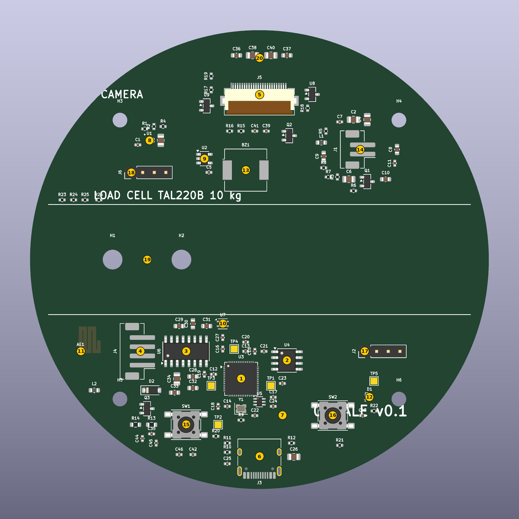
Numbers on the render match the table. Coordinates are millimetres from the top-left of
the board's bounding box, y downwards, centre (50, 50). Generated from placement.json.
#
Item
Ref
Role
Position
1
ESP32-S3R8
U3
dual-core 240 MHz, WiFi + BLE 5, 8 MB PSRAM for the frame buffer
(46, 76)
2
W25Q64 flash
U4
8 MB QSPI program + barcode cache
(56, 72)
3
HX711
U6
24-bit bridge ADC, gain 128, 10 SPS
(34, 70)
4
Load cell connector
J4
4-wire TAL220B pigtail: E+ E- O+ O-
(24, 70)
5
Camera FPC
J5
OV2640 24-pin ribbon, sensor faces up through the glass
(50, 14)
6
USB-C
J3
charge in + native USB: console, flashing, DFU
(50, 93)
7
USBLC6 ESD
U5
data pair clamp right behind the connector
(55, 84)
8
BQ25180 charger
U1
LiPo charger + power path, I2C 0x6A
(26, 24)
9
3.3 V LDO
U2
TLV75733, 1 A — quiet rail for the bridge ADC
(38, 28)
10
SHTC3
U7
temperature for load cell drift compensation
(42, 64)
11
WiFi antenna
AE1
PCB meander with copper cleared on all four layers
(11, 70)
12
Status LED
D1
SK6805 RGB under a hole in the sticker
(74, 80)
13
Buzzer
BZ1
beep on a good barcode read
(47, 30)
14
Battery connector
J1
LiPo lead, cell sits in the base ring
(72, 26)
15
Tare button
SW1
GPIO0 — also the ROM download strap
(34, 86)
16
User button
SW2
GPIO3 — pairing / mode
(66, 84)
17
UART header
J2
rescue console
(73, 70)
18
I2C header
J6
expansion: 3V3, GND, SDA, SCL
(22, 31)
19
Load cell fixed end
2 x M4 through the board into the cell, on 6 mm spacers
(26, 50)
20
Camera window
30 mm clear circle in the printed sticker
(50, 6)
The empty band across the middle is not wasted space — the load cell bolts down there, and
the two M4 holes take the fixed end. Everything else is packed into the two half-discs it leaves.
How it weighs
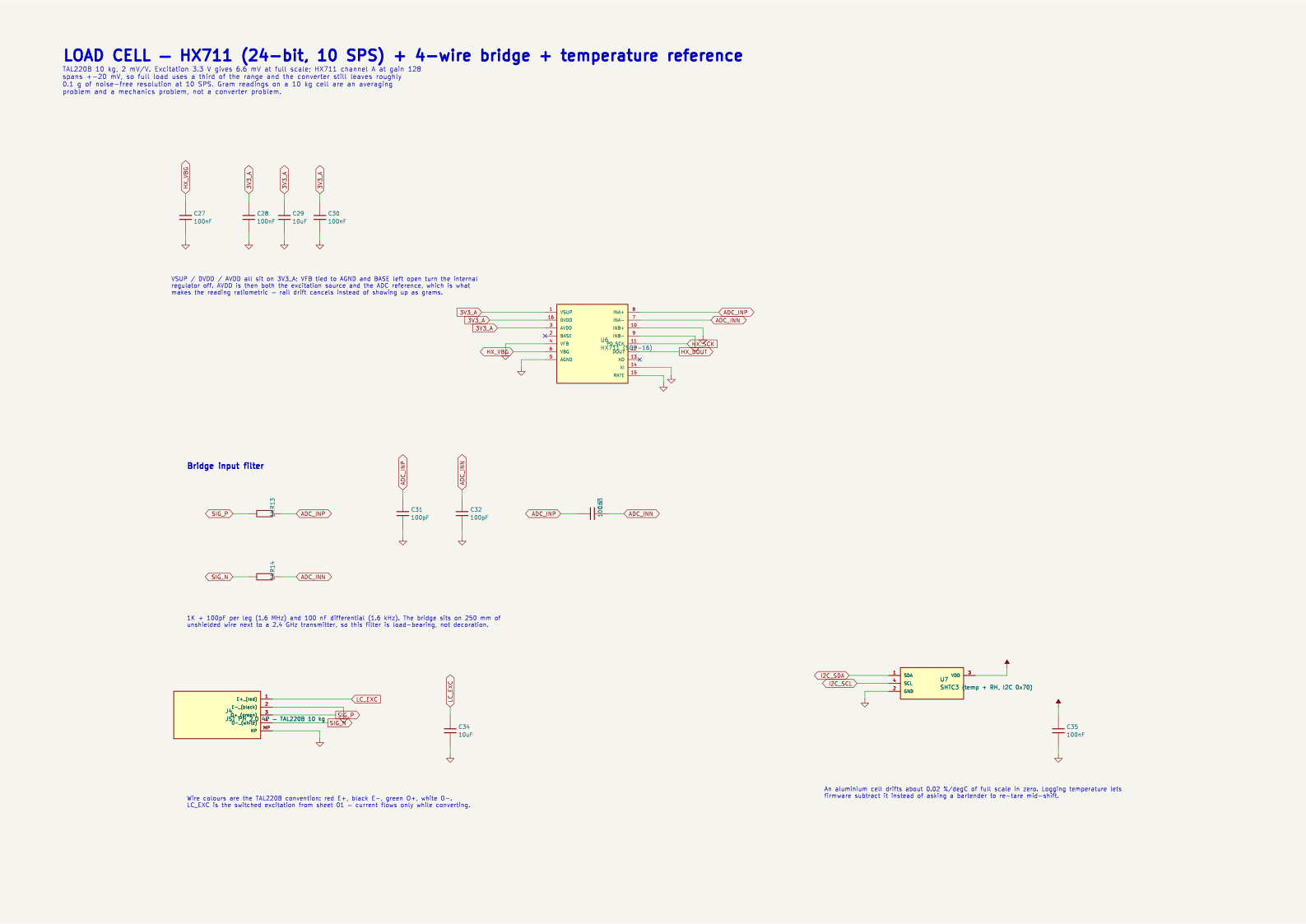
A TAL220B at 2 mV/V on 3.3 V excitation puts 6.6 mV across the ADC at 10 kg.
The HX711 at gain 128 spans ±20 mV, so full load uses about a third of the range and the 24-bit
converter still leaves roughly 0.1 g of noise-free resolution at 10 SPS. Grams, in other words, are an
averaging and mechanics problem here — not a converter problem.
Two details do the real work. First, the ADC reference is AVDD and the bridge excitation comes from
that same node, so the measurement is ratiometric: rail drift cancels instead of arriving as grams.
Second, the excitation is switched by a P-FET, because a 1 kΩ bridge sitting across 3.3 V draws 3.3 mA —
more than everything else on the board draws asleep.
The honest caveat: every number above is the converter's. Creep, hysteresis and corner
load error come from how the cell is bolted down, and they are what actually decides whether the scale
reads the same at 02:00 as it did when it was installed. That is why the board is 1.6 mm with an
aluminium stiffener under the fixed end, and why there is a temperature sensor next to the cell.
Blocks — what each part is doing here
Weighing
HX711 + TAL220B 10 kg
A 2 mV/V bridge on 3.3 V excitation puts 6.6 mV at the ADC at full load. Channel A at gain 128 spans ±20 mV, so full scale uses a third of the range and the 24-bit converter still leaves about 0.1 g of noise-free resolution at 10 SPS. The reference is AVDD and the excitation comes from the same node, so the reading is ratiometric — rail drift cancels instead of arriving as grams. Excitation is switched: a 1 kΩ bridge across 3.3 V is 3.3 mA, more than the rest of the board asleep.
U6, J4, Q3
Barcode
OV2640 DVP camera, facing up
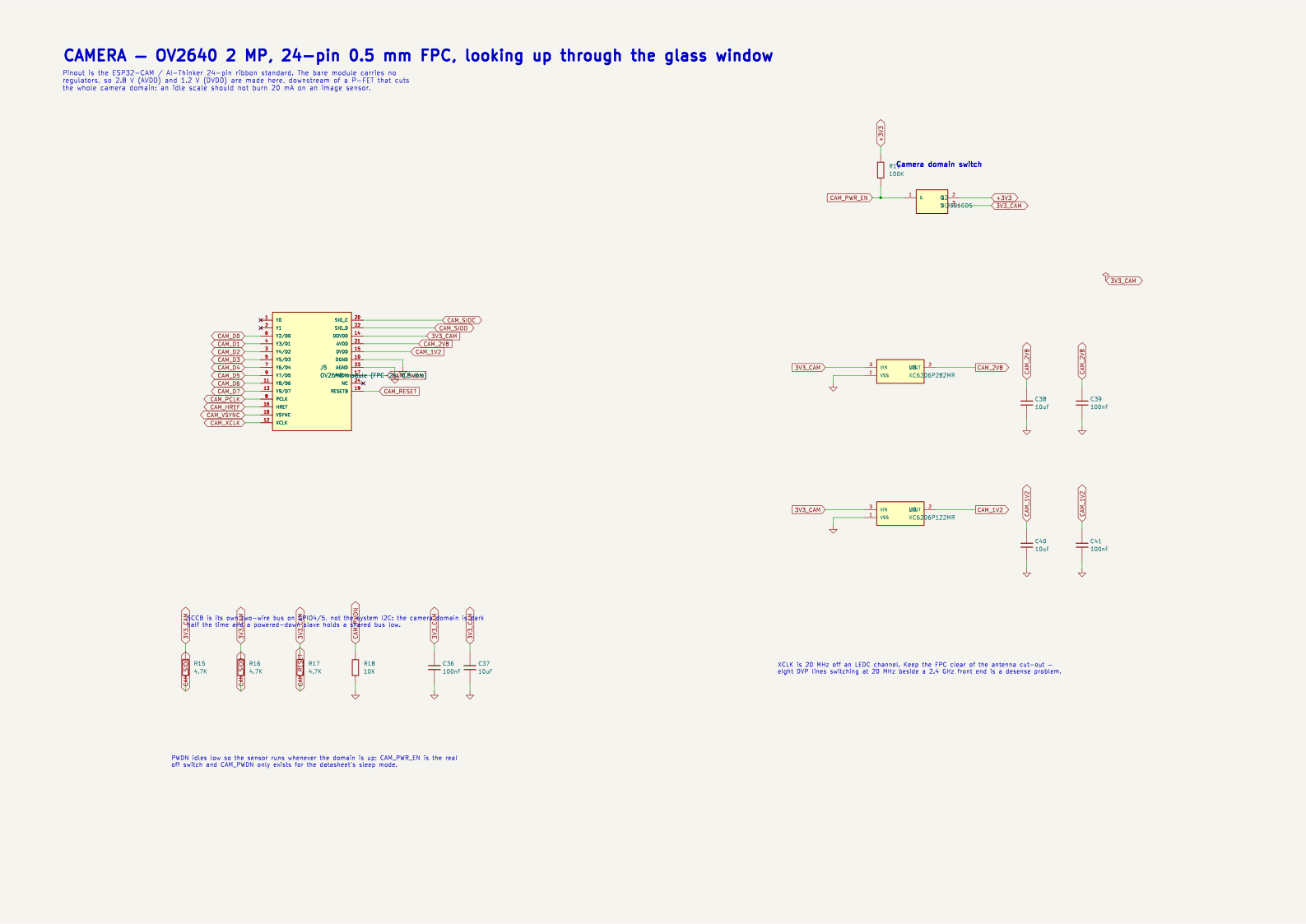
The sensor looks straight up through a 30 mm clear circle in the sticker printed on the underside of the glass. Hold a bottle's barcode or a QR label over that window and the ESP32-S3 decodes it locally — no display, no scanner gun, no phone. The 24-pin 0.5 mm ribbon is the ESP32-CAM standard, so any of the cheap modules drops in. 2.8 V and 1.2 V are made on the board behind a P-FET that kills the whole camera domain between reads.
J5, U8, U9, Q2
MCU
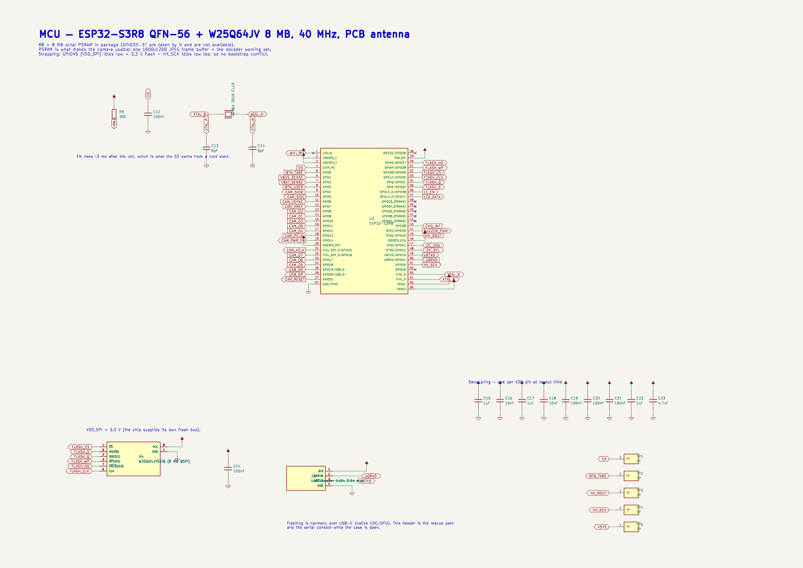
ESP32-S3R8 + W25Q64
Dual-core 240 MHz, WiFi and BLE 5, and the LCD_CAM peripheral that clocks the 8-bit DVP bus. The R8 carries 8 MB of octal PSRAM in package — without it there is nowhere to put a camera frame, and GPIO33–37 are gone to it. 8 MB of external flash holds firmware plus a local barcode → product cache, so a bar with a dead uplink still identifies bottles.
U3, U4, Y1
Power
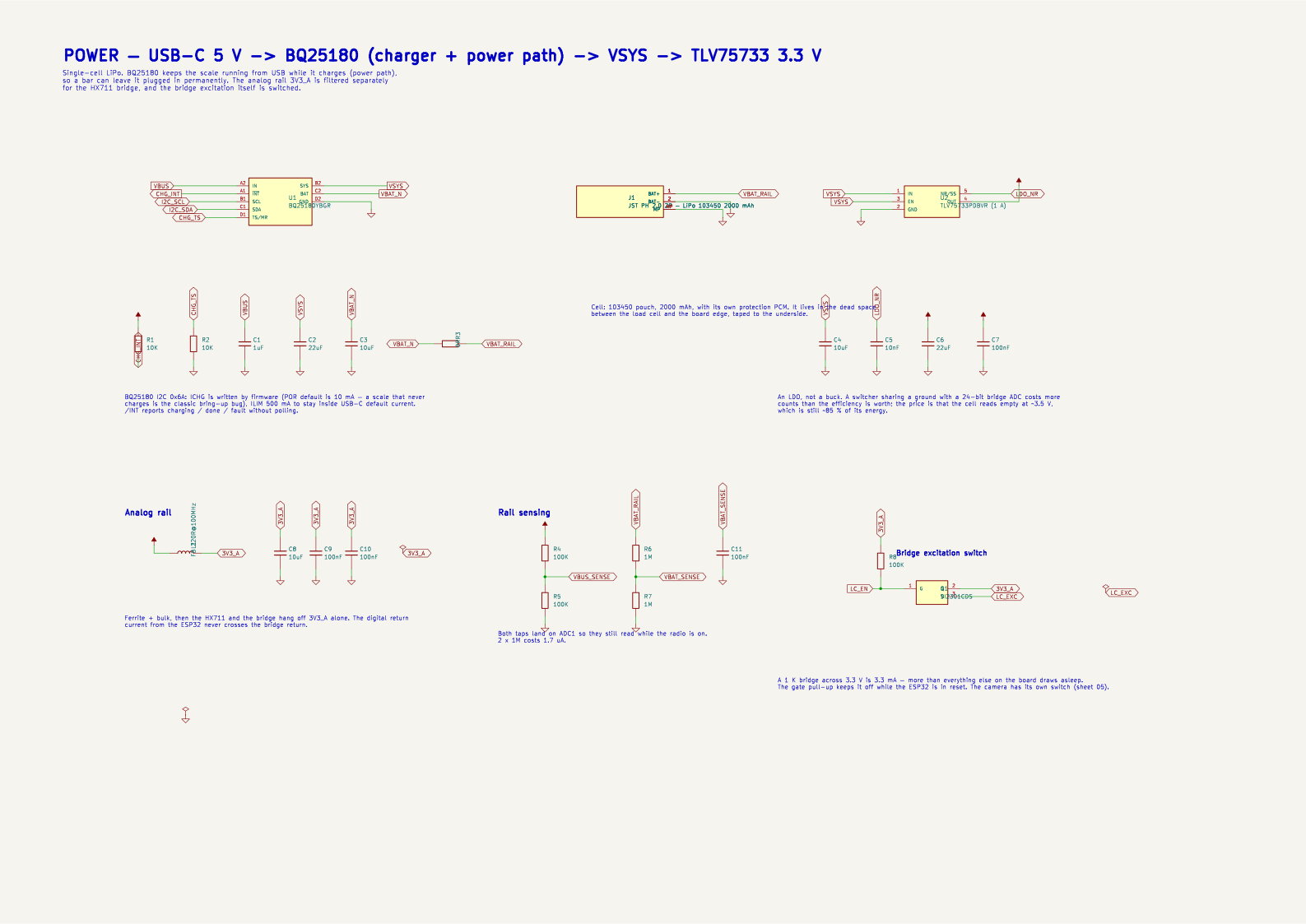
USB-C → BQ25180 → TLV75733
BQ25180 is a charger with a regulated power path, so the scale runs from USB while it charges and can live plugged in permanently. I2C at 0x6A sets charge current and reports state on /INT. The 3.3 V rail is an LDO on purpose: it is also the ADC reference, and a switching node sharing ground with a 24-bit bridge converter costs more counts than the efficiency is worth.
U1, U2, J1, J3
Compensation
SHTC3 temperature + humidity
A strain gauge measures temperature as enthusiastically as it measures force. An aluminium cell drifts roughly 0.02 %/°C of full scale in zero and about 0.01 %/°C in span, so a 10 °C swing between a cold morning bar and a busy Saturday night is worth tens of grams of apparent weight on a 10 kg cell. Logging temperature right next to the cell lets firmware hold a zero-versus-temperature curve and subtract it, instead of asking a bartender to re-tare mid-shift. SparkFun's OpenScale carries a TMP102 for exactly this reason; the SHTC3 costs the same and adds humidity, which is a useful early warning that condensation is getting into a cell rated only IP66.
U7
Feedback
SK6805 RGB + magnetic buzzer
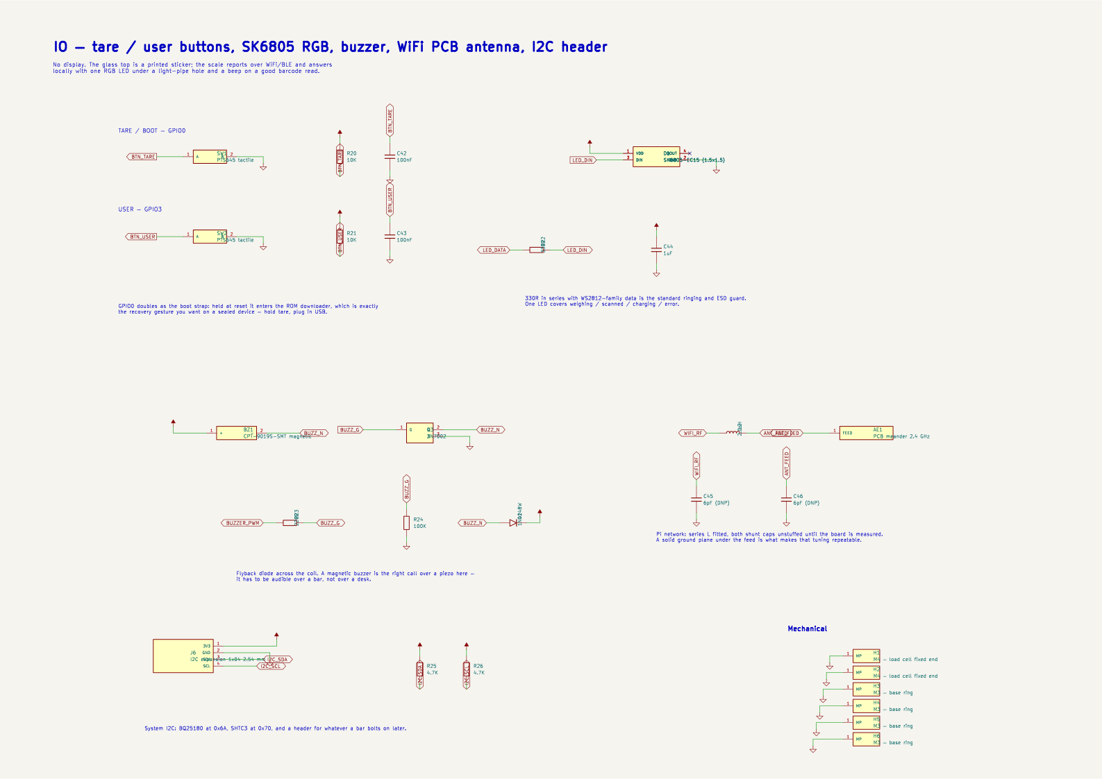
The top is glass, so there is no display to put anything on. One addressable RGB LED under a hole in the sticker covers weighing / scanned / charging / error, and a magnetic buzzer — audible over a bar, unlike a piezo — confirms a good barcode read. Everything else goes out over WiFi or BLE.
D1, BZ1, Q1
Radio
PCB meander antenna, 2.4 GHz
A meander on the west rim with copper cleared on all four layers and a pi network whose shunts ship unstuffed for tuning. The antenna is deliberately as far as the board allows from the camera ribbon: eight DVP lines switching at 20 MHz beside a 2.4 GHz front end is a desense problem.
AE1, L2
Expansion
I2C header + UART header
Two 1×04 headers: the system I2C bus (charger, SHTC3, anything a bar bolts on later) and a rescue console. Normal flashing is over USB-C through the S3's own USB PHY, so no bridge chip.
J2, J6
Against the obvious alternatives
The closest published thing to this board is SparkFun's OpenScale — an ATmega328P, an HX711 and a
temperature sensor on a breakout that speaks serial. It is a good design, and it is the reason there is a
temperature sensor on this board at all. The gap is everything after the measurement: OpenScale hands you
grams over a USB cable and stops there, and the cheap HX711 module kits do not even do that much.
0Scale
SparkFun OpenScale
HX711 module kit
Microcontroller
ESP32-S3R8 — dual-core 240 MHz, 8 MB PSRAM
ATmega328P — 8-bit, 16 MHz
none: the module is only an ADC
Bridge ADC
HX711, 24-bit
HX711, 24-bit
HX711, 24-bit
Temperature compensation
SHTC3 (temperature + humidity) beside the cell
TMP102 on board, plus a DS18B20 header
none
Connectivity
WiFi + BLE, and USB-C CDC over the S3's own USB PHY
USB serial at 9600 bps, and that is all
four wires to your own microcontroller
Bottle identification
OV2640 camera reads barcodes and QR codes through the glass
—
—
Power
LiPo + USB-C charging with a power path; runs while charging
5 V from USB, 80–100 mA, no battery
borrowed from the host board
Mechanics
The Ø100 board is the chassis: the cell bolts to it, glass on top
Rectangular breakout — bring your own everything
Bring your own everything
Load cell
Designed around a specific one: TAL220B, 10 kg, 4-wire
Not included; supports 4- and 5-wire cells
Usually bundled with a small cell
Price
≈$45–60 per unit at 100 off, including cell and glass
$34.95, board only
a few dollars, module only
Where the difference lands: this is an appliance, not a component. It ships as the platform a
bottle stands on, it knows which bottle that is, it runs on its own battery and it reports over the network —
so a bar gets pour-level inventory instead of a number on a serial terminal.
Mechanical stack
Tempered glass Ø110 × 5 mm — printed sticker underneath, 30 mm clear camera window5.0 mm
M5 stud + platform disc on the cell's live end8.0 mm
Aluminium spacers under the fixed end (2 × M4 into the board)6.0 mm
PCB — 4 layers, 1.6 mm, Ø100 mm; this is the chassis the cell bolts to1.6 mm
Base ring (aluminium or ABS) — holds the LiPo, the stiffener and 4 silicone feet14.0 mm
Total≈47 mm
The load path is glass → stud → cell live end → cell → fixed end → spacers → PCB →
base ring → feet. The board carries the full 10 kg in bending, which is why it is 1.6 mm rigid with a
60 × 20 × 3 mm aluminium stiffener under the fixed end: FR4 flex shows up directly as non-linearity.
The sticker printed on the underside of the glass carries the branding and leaves a 30 mm clear circle
over the camera plus a small hole over the status LED. Both positions come out of placement.json,
so the artwork is generated, not measured off a photo.
The battery lives in the base ring, not on the board — that keeps the whole top face available for
electronics and the load cell.
USB-C sits on the south rim. The plug clears the board because the receptacle's opening is above the
board plane; the base ring carries the cut-out.
Schematics (KiCad 10, ERC 0 errors)
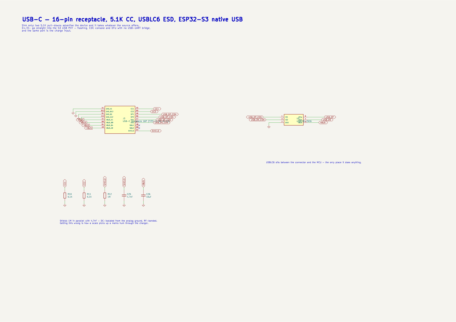
Vector — zoom in the browser. Every sheet is emitted by
generator/gen_0scale.py; the generator refuses to write a sheet where two wires
cross without being one net, which is the failure mode that makes generated schematics untrustworthy.
01-powerPower — USB-C, charger, rails
02-mcuMCU — ESP32-S3R8 + flash
03-usbUSB-C — connector, CC, ESD
04-loadcellLoad cell — HX711 + bridge
05-cameraCamera — OV2640 DVP
06-ioIO — buttons, LED, buzzer, antenna
Bill of materials
Unit prices in USD at small quantity. lcsc = verified LCSC/JLCPCB
listing, est = estimate (±30 %). 12 lines are marked
verify: they have no confirmed part number yet and must be checked against a live
listing before ordering.
$155–255cell, glass, battery, camera, base ring × 5
$344–501total for 5, excluding shipping
$69–100per prototype
Standard PCBA is required: the 0.4 mm pitch QFN-56 and the DSBGA-8 charger are past Economic assembly.
Hand steps per unit: load cell and its spacers, the glass and its sticker, the battery, the camera
ribbon, the base ring. Call it 15 minutes once the jig exists.
At 100 units the SMT parts drop roughly 35 %, the PCB lands near $3 each and the fixed PCBA cost
amortises — order of $45–60 per scale including the cell and the glass.
Files and how it is generated
hardware/0scale/generator/gen_0scale.py — all six schematic sheets
floorplan_0scale.py — placement: circle blockers, the load cell band, anchors
pcbgen_0scale.py — the board: round outline, zones, keep-outs (runs under KiCad's python)
bom_cpl_0scale.py — JLCPCB BOM / CPL / hand-assembly list
annotate_0scale.py — the numbered render and legend.json above
pipeline.sh build | route | finish | all — the whole chain, reproducible
Nothing here is drawn by hand. Changes go into the generator and the chain is re-run;
the .kicad_sch and .kicad_pcb are outputs, not sources.
That is the same discipline as the 0Card project this borrows its schematic engine from.
Open questions
LCSC codes
12 of the 44 BOM lines still carry no verified LCSC number. The generator prints them on every run and the BOM below marks them — they must be checked against a live listing before ordering.
CPL rotations
Offsets follow the JLCKicadTools rotation table (SOT-23 −90°, SOT-363 180°, QFN/SON 270°). JLC publishes no official table, so the 3D preview has to be checked before confirming — the SK6805 and the USB-C receptacle are the usual offenders.
Antenna tuning
The pi network ships with the series inductor fitted and both shunt caps unstuffed. Tune on a VNA with the glass and the cell in place: an aluminium bar 20 mm above the antenna detunes it, and no amount of simulation substitutes for measuring that.
LDO thermals
Worst case is ~0.5 W in a SOT-23-5 — charging at 4.5 V with the camera and radio both up. It is a burst, not a steady state, but it needs measuring. Fallback: a WSON package, or a small buck ahead of the LDO.
Mechanical creep
Every gram claim here is the converter's, not the assembly's. Creep, hysteresis and corner load error come from how the cell is bolted down. Measure them on the first build before the resolution number means anything.
Camera field of view
An OV2640 with the stock lens sees roughly 34 mm across at the glass. That sets the sticker window at 30 mm and means barcodes are read held above the plate, not lying on it.